A Quick Toolpost Drill Spindle
I've had a job on the backburner for ages that needed accurate radial holes drilled after turning in the chuck. Not having a dividing head, I thought the way to go would be a milling/drilling spindle for the toolpost. Well, that's quite a big project in itself so I decided to make a 'quicky' drilling spindle out of a spare drill motor (electric drill) spindle.
I pressed the gear off the spindle and replaced it with a pulley to take a sewing machine belt. I had a handy block of steel left over from cutting out the rear toolpost I affixed a bit of 8mm square steel to the side so it could mount like a tool in the toolpost. I then drilled and bored it so mounted, using a boring tool in the 4 jaw chuck to bring it to size.
This project took a week of evenings of hard slog, but I had a deadline to get the other project out by Friday. At the beginning too, I did not have the camera handy so only later stages are shown here.
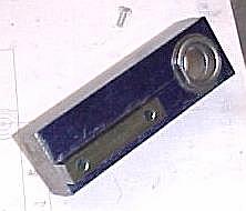
A view of the partially completed body. The square strip at bottom left clamps like a tool in the toolpost. The bearing is glued in with stud lock (all I have on hand) after boring the hole with the raw block attached to the toolpost. A boring tool was held in the 4 jaw chuck for this operation.
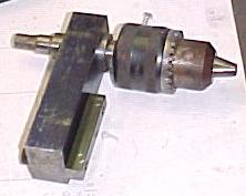
The spindle in the body. This shot does not show the thrust bearing which was made and fitted between the chuck and the body.

Boring the hole in the pulley blank for the spindle.
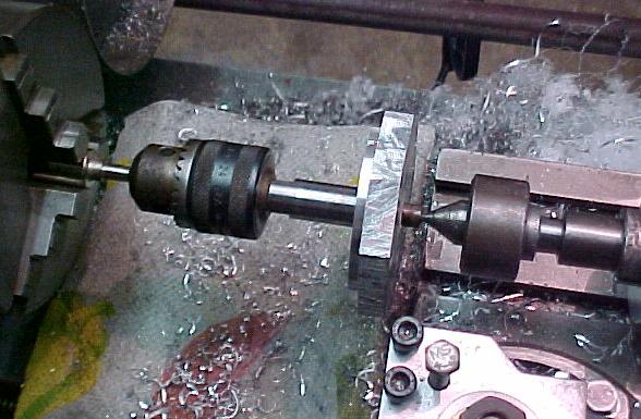
The spindle mounted 'between centers' for turning the pulley. A bit of scrap was mounted in the chuck and turned in place to run absolutely true. The drill chuck was then fastened to this true spigot. The other end of the spindle had a pre-existing center hole to which I applied the live center. In turning the outside of the pulley I had no trouble at all, but when forming the belt groove I had terrible chatter. Maybe the spigot needed to be bigger? If I had a way of holding the topslide I could have set it at 14.5 degrees (I think that is what the pulley groove is) and used a parting tool to make a square groove before forming the angled sides using the offset topslide. However, the ML7 topslide can only be set to 45 degrees either side of parallel to the axis of the lathe.
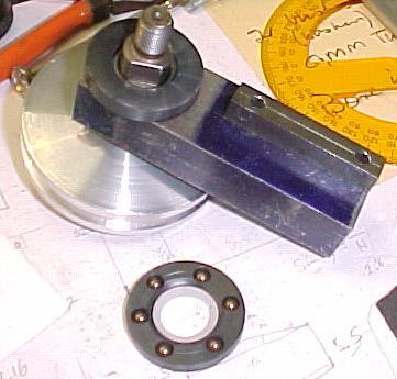
Showing the fabricated thrust bearing. The plastic used is 'Vesconite', a hard and slipery bearing material. I thought to make a plain friction bearing but decided on the balls as I had doubts about the power of he motor. I marked off the disk for 6 holes using a protractor and some guessing, drilled it freehand in the drillpress. The balls bear on the plastic collar fitted to the body, and against the back of the chuck (which I had to true between centers!).
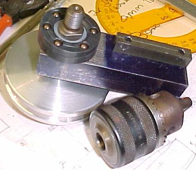
The bearing in place on the spindle prior to fitting the chuck.
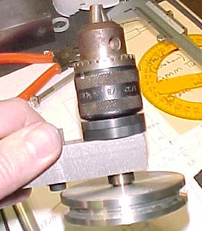
The assembled spindle and main body. Now for the motor mount.....
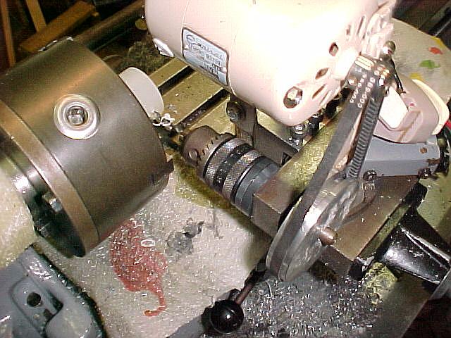
Left hand view of the device fitted to the toolpost ready to drill radial holes in lathe chuck mounted workpieces.
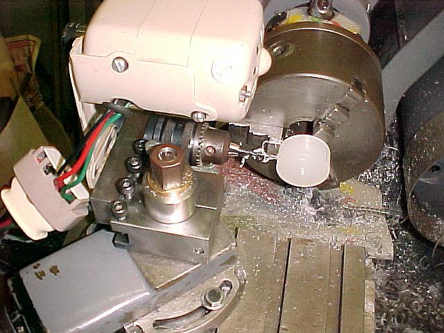
Right or tailstock end view of the device. The power socket was later screwed to the motor bracket using it's own existing holes. I connect it to a sewing machine speed contol pedal for convenient foot control.
This device sufficed to complete the project that needed it, but certain improvements are needed:
- The spindle bearing is very loose. This lets the drill bit wander terribly.
- The motor needs to be modified.
- This motor came off an Emphisal sewing machine and I had to reverse it to suite this application. However, the brushes are skewed for the OTHER direction and I now need to remount them to be skewed for this direction as it runs slow and is very weak compared to its normal power level. In fact the 8mm holes I was drilling in plastic were just about all it could do.
Random Quote
He giveth power to the faint; and to them that have no might He increaseth strengthLast modified: April 25 2026 18:37:02.